For EMS factories, SMT equipment distributors, and electronics manufacturers, choosing a pick and place machine is not only about the highest placement speed on a brochure. The right decision depends on board size, component range, feeder capacity, vision alignment, production mix, and how the machine fits into the full SMT production line.
A modern SMT pick and place machine should handle miniaturized chips, ICs, connectors, BGAs, CSPs, and odd-shaped components with stable repeatability. For consumer electronics, automotive electronics, LED products, telecom devices, medical electronics, or IoT hardware, the machine should support both current BOMs and future upgrades.
Why Pick and Place Machine Selection Matters in SMT Production
The pick and place machine is the core placement unit between solder paste printing and reflow soldering. If the machine is too slow, the reflow oven may wait. If feeder setup is limited, changeover time increases. If placement accuracy is not suitable for fine-pitch components, misalignment, tombstoning, bridging, and rework can affect yield.
For high-volume lines, speed and line balance are often the first concern. For high-mix EMS production, flexibility, fast programming, intelligent feeders, and nozzle changeover can be more important than peak CPH alone.
Check Pick and Place Machine Speed Against Real Throughput
Placement speed is usually shown as CPH, or components per hour. CY Industry's pick and place machine range includes compact modular machines around 46,000 to 47,000 CPH and higher-speed solutions reaching 75,000 CPH, 100,000+ CPH, 130,000+ CPH, and up to 150,000 CPH depending on model configuration and production conditions.
Real output depends on more than rated CPH. Buyers should review heads, nozzles, gantry structure, feeder arrangement, component recognition, PCB transfer time, and changeover frequency. On-the-fly vision recognition can reduce recognition time during movement, while multi-nozzle heads help improve placement density for small components.
For EMS factories, the practical question is: How many finished boards can the line produce per shift with your actual BOM? When evaluating an SMD placement machine, prepare representative BOM files and PCB drawings so the supplier can estimate cycle time and recommend one flexible mounter, two balanced mounters, or a high-speed plus flexible combination.
Match Pick and Place Machine Accuracy to Component Size
Accuracy becomes more critical when products use 0201, 01005, 008004, fine-pitch BGAs, CSPs, small connectors, or densely populated PCBs. CY Industry's product range includes machines with placement accuracy levels such as ±35μm, ±25μm, and ±15μm depending on model class, while some models are designed for ultra-miniature components and micro-BGA applications.
For general LED boards, household electronics, power supply boards, and standard control boards, a flexible SMT machine may be sufficient if the component range and PCB size match the requirement. For automotive electronics, medical devices, communication modules, and compact IoT products, buyers should pay closer attention to mounting accuracy, vision recognition, calibration stability, and force control.
Evaluate Feeders, Nozzles, and Component Range for the SMT Pick and Place Machine
Feeder capacity affects both production flexibility and setup efficiency. CY Industry's machine options include feeder capacities such as up to 96 component types, 112 feeder inputs, or 120 feeders based on 8mm tape feeder conversion, depending on the model. This matters for EMS factories handling frequent product changes and complex BOMs.
Feeder planning: Check tape feeders, tray components, stick feeders, and docking cart options.
Nozzle planning: Confirm support for chips, ICs, connectors, LEDs, lenses, BGAs, CSPs, and odd-shaped parts.
Changeover planning: Review barcode setup, feeder verification, CAD-driven programming, offline programming, and component confirmation.
Component range should be reviewed together with feeder capacity. Some machines handle ultra-small chips, while others support larger connectors, ICs, LED lenses, or wider rectangular parts. If the factory produces both compact modules and larger industrial control boards, a multi-functional pick and place PCB machine is usually more practical than a machine optimized only for simple chip placement.
Review Vision System and Inspection Features Before Buying a Pick and Place Machine
The vision system determines how reliably the machine recognizes components and aligns them before placement. Flying vision, scan cameras, multi-camera options, 3D inspection, and real-time error detection can improve process stability. For fine-pitch ICs and BGA/CSP applications, high-speed and high-accuracy recognition is especially important.
Advanced models may include force control to protect delicate components and reduce tombstoning or misalignment. Some systems also support nozzle contamination checks, component monitoring, and incorrect component prevention. These functions are valuable where rework cost is high or traceability is required.
| Selection Factor | What Buyers Should Check | Why It Matters |
|---|
| Speed | Rated CPH, real cycle time, head design | Avoids SMT line bottlenecks |
| Accuracy | Placement accuracy, fine-pitch support, calibration | Reduces dense PCB defects |
| Feeders | Feeder count, docking cart, tray support | Improves high-mix flexibility |
| Vision System | Flying vision, scan camera, BGA/CSP recognition | Improves placement reliability |
| Line Integration | PCB size, conveyor direction, reflow matching | Supports smoother line layout |
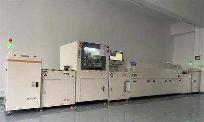
Consider Pick and Place Machine Integration with the Full SMT Line
A pick and place machine should not be selected as an isolated unit. It must work with the solder paste printer, PCB loader, conveyor, SPI, AOI, reflow oven, and PCB unloader. Some projects may also require conformal coating, potting, DIP insertion, or wave soldering after SMT assembly.
Before purchase, confirm PCB dimensions, board thickness, component height, line direction, workshop space, power supply, air supply, and expected daily output. Compact machines may fit smaller production areas, while high-speed dual-lane or multi-machine configurations may be better for mass production. Matching upstream and downstream equipment helps reduce waiting time, manual handling, and process instability.
Conclusion
Choosing the right pick and place machine requires a balanced review of speed, accuracy, feeder capacity, component range, vision alignment, and SMT line integration. For B2B buyers, the best machine is the one that matches real PCB products, BOM complexity, production volume, and future process requirements. To discuss a suitable SMT pick and place machine configuration, send your PCB size, BOM, target output, component package range, and preferred line layout to CY Industry's engineering team.
FAQ
1. What is the most important factor when choosing a pick and place machine?
The most important factor is the match between your real production requirements and the machine configuration. Buyers should compare PCB size, component package range, BOM complexity, target output, feeder capacity, and accuracy requirements instead of focusing only on maximum CPH.
2. Is higher CPH always better for SMT production?
Not always. Higher CPH is useful for mass production, but high-mix EMS factories may benefit more from fast changeover, flexible feeder setup, CAD-driven programming, and stable vision alignment. Real line output should be evaluated by actual BOM and PCB data.
3. What accuracy level should a pick and place machine have?
It depends on the component packages used in your products. Standard PCBs may not require the highest accuracy, while fine-pitch BGAs, CSPs, 01005, 008004, and compact IoT modules need stronger placement accuracy, recognition, and calibration stability.
4. How many feeders does an SMT pick and place machine need?
The required feeder count depends on BOM complexity and changeover frequency. EMS factories with many product types should consider higher feeder capacity, docking carts, tray support, and verification functions to reduce setup time and placement errors.
5. Why is the vision system important in a pick and place PCB machine?
The vision system recognizes component position, orientation, and alignment before placement. Good vision recognition helps improve placement reliability, especially for fine-pitch ICs, BGAs, CSPs, odd-shaped components, and high-density PCB assemblies.
6. What information should buyers provide before requesting a machine recommendation?
Buyers should provide PCB size, board thickness, BOM, component package range, target output, product mix, workshop space, power and air supply conditions, and preferred line layout. These details help the supplier recommend a practical pick and place machine configuration.