For PCB manufacturers and EMS providers, choosing an automatic insertion machine is not simply a comparison of placement speed. The right system must match the component mix, PCB design, production volume, changeover frequency, soldering process, and available technical support.
A machine that performs well on a stable, high-volume board may be inefficient for a factory producing many low-volume assemblies with axial, radial, DIP, and odd-form parts. Buyers should therefore define their actual production requirements before comparing quotations.
What Does an Automatic Insertion Machine Do?
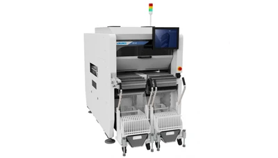
Automatic insertion equipment places through-hole component leads into pre-drilled PCB holes before wave or selective soldering. Depending on the configuration, the machine may also cut, form, and clinch the leads so the components remain stable during transfer and soldering. For manufacturers evaluating a suitable pcb insertion machine, selecting the right insertion technology based on component type and production requirements is essential.
Automation can reduce manual bottlenecks, inconsistent orientation, bent leads, missed components, and labor requirements. However, the return depends on how many placements on each board can be automated. Selecting the right automatic insertion machine can therefore improve placement consistency while reducing dependence on manual assembly.
When evaluating a tht machine, calculate the percentage of through-hole components the system can handle. High rated speed offers limited value if most parts must still be inserted manually.
Match the Machine Type to the Component Mix
The first question should be: “Which components must the machine handle?”
An axial insertion machine is designed for parts whose leads extend from opposite ends of the body, such as many resistors, diodes, and jumper wires. Buyers should verify supported body sizes, lead diameters, insertion spans, reel formats, and lead-forming requirements.
Radial insertion equipment handles components with leads extending from the same side, including certain capacitors, LEDs, transistors, and filters. Important checks include lead pitch, body dimensions, polarity recognition, component height, and feeder format.
A dip inserter is intended for dual in-line packages or similar components with parallel rows of pins. Because some suppliers use “DIP insertion” more broadly for through-hole assembly, the quotation should clearly list supported package dimensions, pin counts, and feeding methods.
For mixed assemblies, buyers may need a flexible machine with multiple heads and feeders or a production cell combining dedicated systems. The best approach depends on annual volume, product stability, available floor space, and the amount of manual work that remains.
Compare Actual Output, Not Only Rated Speed
Published speed is normally measured under controlled conditions. Real output is also affected by PCB transfer, feeder indexing, board size, insertion sequence, changeovers, inspection, and stoppages.
Ask the supplier to estimate output using your bill of materials, PCB files, component packaging, and batch size. Compare:
Insertions and boards per hour
Automated component coverage
Product changeover time
Feeder replenishment requirements
Expected misinsertion or reject rate
Planned maintenance and uptime
For high-mix production, fast programming and short changeovers may matter more than maximum speed. For stable, high-volume products, dedicated feeders and optimized sequences may provide a lower cost per board.
A sample trial using representative boards and components is the strongest way to verify cycle time, insertion quality, operator workload, and remaining manual processes.
Evaluate Accuracy, Vision, Feeders, and Clinching
Insertion accuracy must suit PCB hole size, component lead geometry, and board tolerances. The system should guide leads into the correct holes without bending them, damaging components, or stressing the PCB.
Vision systems may verify PCB position, hole location, component orientation, and polarity. Ask what the cameras inspect, how position correction works, and whether inspection data can be stored for traceability.
The feeder system is equally important. Confirm support for reels, tubes, trays, bulk feeding, or custom feeders. Review feeder capacity, replenishment time, changeover method, and expansion options.
Lead clinching keeps components in position before soldering. Check adjustable lead length, clinch direction, under-board clearance, tool life, and access for cleaning or replacement. Tall, heavy, fragile, or irregular parts should receive a component-by-component feasibility review.
Check PCB Compatibility and Line Integration
Confirm the machine’s minimum and maximum PCB size, board thickness, allowable warpage, edge clearance, tooling requirements, panel format, component height, and under-board support.
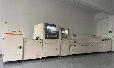
For inline production, review conveyor direction, transfer height, communication interfaces, buffering, and compatibility with wave or selective soldering equipment. Hybrid SMT/THT factories should also decide where insertion will occur after surface-mount assembly.
Offline equipment may suit smaller batches, but loading, unloading, inspection, and board transfer labor must be included in the capacity calculation.
Programming functions also influence daily operation. Useful capabilities include coordinate import, recipe management, revision control, feeder monitoring, alarm records, and barcode-based product verification.
Review Maintenance, Support, and Total Cost
Automatic insertion equipment combines motion systems, cutters, forming tools, feeders, cameras, and software. Long-term performance therefore depends on maintenance access and supplier support.
Before purchasing, confirm spare-parts availability, consumable tooling, remote diagnostics, software updates, installation, operator training, maintenance training, and service response. Request a recommended spare-parts package for the first year of production.
The total cost should include the machine, feeders, tooling, installation, shipping, utilities, training, maintenance, spares, changeover labor, and expected utilization. The lowest purchase price does not always produce the lowest cost per inserted component.
Prepare a Clear RFQ and Acceptance Plan
A detailed request for quotation helps suppliers recommend the correct configuration. Provide annual volume, shift pattern, target output, PCB drawings, coordinate files, bill of materials, component datasheets, packaging formats, soldering method, factory layout, and quality requirements.
The acceptance plan should define measurable criteria, including automated component coverage, cycle time, insertion quality, component damage, lead forming and clinching, board transfer, recipe changeover, and trial-run duration.
Choosing an automatic insertion machine is ultimately a process-matching decision. Buyers who evaluate actual boards, components, volumes, and line conditions are more likely to achieve stable output and a practical return on investment.
FAQ About Automatic Insertion Machines
What Is the Difference Between an Automatic Insertion Machine and a Pick-and-Place Machine?
A pick-and-place machine normally mounts surface-mount components onto solder paste. An automatic insertion machine places component leads through PCB holes. Many mixed-technology boards require both processes.
When Should a Factory Invest in an Axial Insertion Machine?
It is suitable when axial components represent a significant share of recurring production and manual insertion restricts output or consistency. Component packaging, insertion span, PCB design, and annual volume should be verified first.
Can One Machine Insert Axial, Radial, and DIP Components?
Some flexible systems support several component categories through different heads and feeders, while other machines are dedicated to one family. Compatibility should be confirmed with actual samples and drawings.
What Information Should Be Sent to the Supplier?
Send PCB dimensions and files, the bill of materials, component datasheets, packaging details, target capacity, batch sizes, soldering method, and line layout. This allows the supplier to evaluate automation coverage and required tooling.
How Should Buyers Compare Quotations?
Compare component coverage, verified output, changeover time, feeder configuration, insertion and clinching quality, line integration, training, warranty, spare parts, service response, and total ownership cost—not only rated speed or machine price.


 Call us on:
  Email Us:
  Building 2, Xingye 1st Road, Fenghuang Community, Fuyong Street, Bao 'an District, Shenzhen, Guangdong, China.